Seismic Horizon Probe
Seismic Horizon Probe for E&P Applications
The Open Inventor toolkit has many features implemented specifically for E&P applications. For example, Open Inventor allows E&P applications to create a wide variety of "probes" to help users explore and understand their seismic data. A "box" probe can be created using the SoROI node. This node can define a simple region of interest or a "chair cut" using either opaque skin rendering or full volume rendering. In addition, box probes can be interactively "dragged" through the volume using an SoROIManip node. But this is just the beginning. An application can use Open Inventor geometry nodes to define a probe with almost any shape. For example, a probe that renders seismic within a specified radius of a well path. In this article we will present a powerful special case: the seismic horizon probe.
Horizons
In seismic data, horizons are reflectors (seismic events) that represent a change in rock properties across a boundary between two layers of rock.
Single horizon
Horizons are often rendered using a surface mesh defined by triangles. But a single horizon defined on a large seismic volume can require many millions of triangles and an interpretation project may include many horizons. Storing X, Y, and Z values for every vertex uses a lot of CPU memory and rendering many large horizons can be too slow even on modern GPUs.
Open Inventor provides a better way!
The SoHeightFieldGeometry node optimizes memory usage. The horizon surface is stored as a height field (implicit grid) so that only the Z values need to be stored. In addition, the height field data can be stored as "tiles" in a multi-resolution hierarchy, similar to the way that Open Inventor efficiently manages very large volume data sets.
The SoHeightFieldRender node solves the performance problem. It uses dynamic tesselation on the GPU to generate the triangles. In addition, it takes advantage of the multiple resolution levels to generate fewer triangles when the user is interacting with the scene. This allows users to display and interact with as many large horizons as they need.
Two horizons
Uniform Grid Clipping
Open Inventor provides multiple tools for clipping seismic volume data, including: clip to plane, clip to box, clip to arbitrary geometry, and clip to volume mask. To display a horizon probe we will use another tool called uniform grid clipping.
The SoUniformGridClipping node defines a uniform grid of "height" values that can be used to clip volume rendering above or below the grid. That should sound very similar to a horizon height field and it is! A uniform clipping grid can be oriented on any axis and can also be generated very conveniently by rendering any shape, such as a horizon, and projecting it onto a surface. The actual grid is stored in a very compact efficient way.
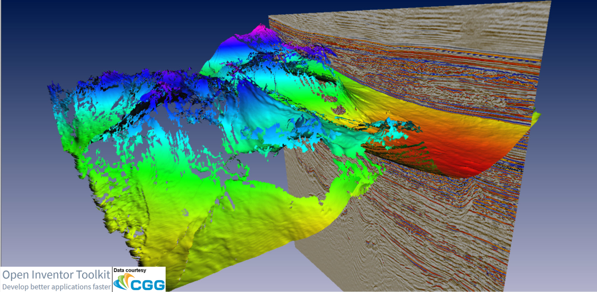
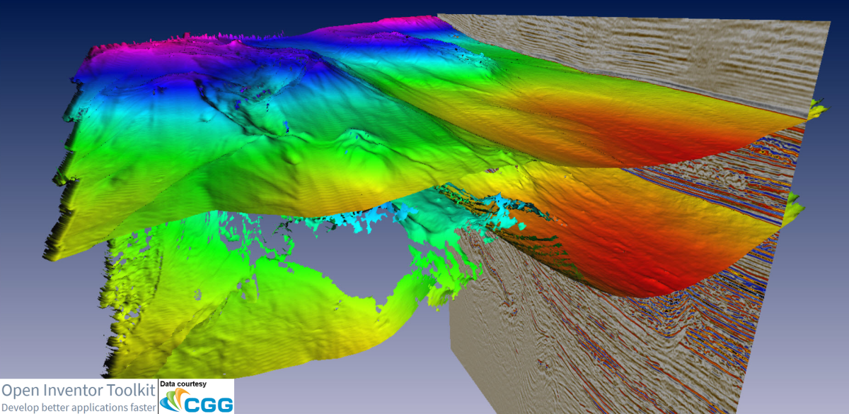
The uniform grid clipping node has a property called "thickness". The thickness property expands the clipping surface in both directions perpendicular to the surface. For example, a completely flat clipping surface, with thickness greater than zero, generates a "slab" or "thick slice". In general, the thickness property allows the user to see voxels within a specified distance from a horizon surface, as shown here.
Single horizon volume probe
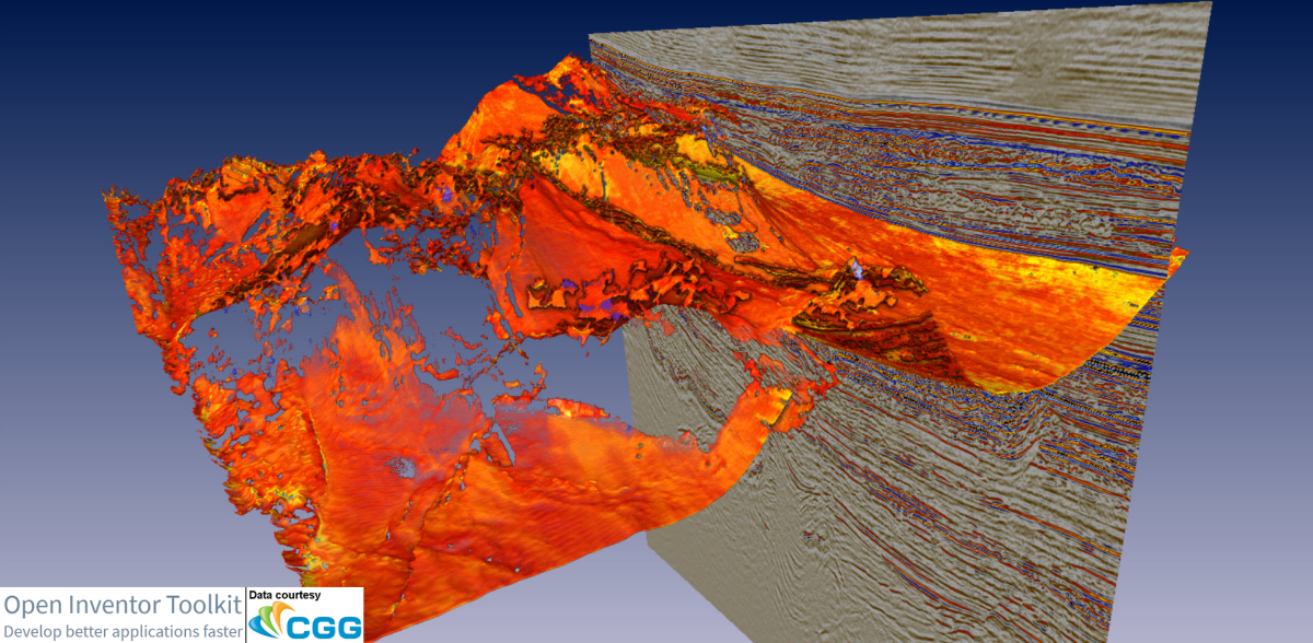
Using this node's 'clipAbove' and 'clipBelow' properties we can use a pair of uniform clipping grids to display a horizon probe showing only the voxels between two horizons.
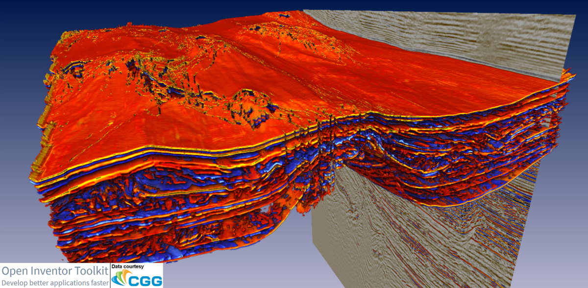
Dual horizon volume probe
An example is provided in the Open Inventor SDK installation in the directory examples\source\VolumeViz\horizonClipping


